


Audi Q5 8R Virtual Cockpit-uppgradering: Komplett installationsguide för 2009–2017 Q5 & SQ5
Hur installerar man en Audi Q5 8R Virtual Cockpit på 2009–2017-modeller?
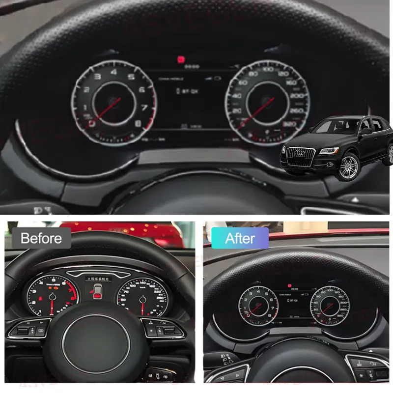
Kort svar
För en kompatibel 2009–2017 Audi Q5 / SQ5 8R med original mekanisk instrumentkluster, är eftermonteringsvägen att dokumentera fordonets ursprungliga skick, ta bort fabriksklustret, överföra den nödvändiga originalelektroniken till den nya digitala klusterenheten, ansluta den matchade kabelstammen utan klippning, hålla uppdaterings-USB:t åtkomligt, strömtesta klustret före slutlig stängning och sedan slutföra de nödvändiga kontrollerna av display och bränslekalibrering.
Detta är en fordonsspecifik verkstadsprocedur, inte ett universellt kompatibilitetslöfte. Den exakta levererade klusterversionen och fordonets utgångsläge avgör fortfarande de slutliga funktionerna och menyvägarna.
Denna sida är en iKAGOO Audi Q5 8R Virtual Cockpit Retrofit installationsguide för kompatibla 2009–2017 Audi Q5 / SQ5 8R-modeller med det ursprungliga mekaniska instrumentklustret. Den är utformad som en verifierbar verkstadsprocedur, inte som en allmän kompatibilitetsgaranti, och den ska inte tolkas som ett löfte om att varje funktion, varningsläge eller fordonsvariant beter sig identiskt.
Plug-and-Play gräns: Plug-and-Play innebär ingen kapning eller skarvning av fordonets originalkablage. Det kräver fortfarande demontering av instrumentpanelen, överföring av originalkort, inspektion av hjälpkort där tillämpligt, dragning av USB-kabel, verifiering av inställningar och kalibrering.
Audi Q5 8R modellårs-fokus: Denna guide är skriven för Audi Q5 / SQ5 8R-generationen, som generellt såldes som 2009–2017 på de europeiska och nordamerikanska marknaderna. Den gäller endast kompatibla fordon med rutten för det ursprungliga mekaniska klustret. Alla gemensamma referenser till Audi / Volkswagen-inställningar ska endast tillämpas när den levererade Q5-klusterversionen använder samma menysökväg.
Vilka Audi Q5 8R-modeller täcker denna installationsguide för Virtual Cockpit?
Direkt svar
Denna installationsväg är skriven för kompatibla först generationens Audi Q5 / SQ5 8R-fordon med original mekanisk instrumentkluster. För iKAGOO-hårdvara är det fungerande passningsintervallet i denna guide fortfarande 2009–2017. Fordonet måste fortfarande bekräftas utifrån originalklustret och instrumentpanelens foton innan beställning eller demontering.
Audi sålde första generationens Q5 under olika motor-, utrustnings- och marknadsföringsnamn i Europa och Nordamerika. Dessa namn är användbara för att identifiera fordonet, men motornamn, utrustningsnivå eller modellbeteckning ensam bevisar inte klusterkompatibilitet. Den fysiska originalklustervägen är den avgörande referensen.
Nordamerika: Audi Q5 / SQ5 8R
- Audi Q5 8R / första generationens Q5: Amerikanska modellår 2009–2017.
- Vanliga Q5-namn: Q5 2.0T / 2.0 TFSI quattro, Q5 3.2 FSI quattro, Q5 3.0T / 3.0 TFSI quattro, Q5 TDI / 3.0 TDI clean diesel quattro och Q5 hybrid quattro.
- Prestandamodell: Audi SQ5 8R, vanligen identifierad i Nordamerika som 3.0 TFSI / 3.0T quattro-modellen.
- Utrustningsnamn som ses i USA och Kanada: Premium, Premium Plus och Prestige. Utrustningsnamnet ersätter inte den fotobaserade passformsbekräftelsen.
- Inte denna generation: Amerikanska modellår 2018 och senare Q5-fordon tillhör nästa generations rutt och får inte använda denna installationsprocedur.
Europa: Audi Q5 / SQ5 8R
- Audi Q5 8R / första generationens Q5: den första generationen introducerades i Europa 2008; denna iKAGOO-guide håller en 2009–2017 bekräftad försäljnings-/passformsgräns. Ett fordon registrerat 2008 kräver individuell bekräftelse innan denna guide används.
- Vanliga bensinnamn: Q5 2.0 TFSI, Q5 3.2 FSI, Q5 3.0 TFSI och Q5 hybrid quattro.
- Vanliga dieselnamn: Q5 2.0 TDI och Q5 3.0 TDI quattro.
- Prestandanamn: SQ5 TDI, SQ5 TDI plus och, på tillämpliga marknader, SQ5 TFSI. Dessa namn beskriver fordonsversionen; originalinstrumenthuset måste fortfarande matcha den supportade rutten.
- Karossgenerationsbeteckningar: Q5 8R, Q5 Mk1, första generationens Q5, Q5 8R före ansiktslyftning och Q5 8R efter ansiktslyftning kan alla användas av ägare och verkstäder.
Användbara sök- och identifieringstermer: Audi Q5 8R virtual cockpit, Audi Q5 digital instrumentkluster, Audi Q5 LCD-kluster, Audi Q5 8R digital instrumentpanel, Audi Q5 Mk1 virtual cockpit, Audi SQ5 8R digitalt kluster, Audi Q5 2009–2017 instrumentkluster-retrofit.
Kompatibilitetsgräns: Dessa namn ingår så att europeiska och nordamerikanska ägare kan identifiera rätt generation. De är inte ett påstående att varje motor, utrustningsnivå, landspecifikation eller fabriksalternativ använder identisk elektronik.
Vad måste bekräftas innan något demonteringsarbete påbörjas?
- Exakt fordonsmodell och modellår.
- Original mekaniskt instrumentkluster fotograferat medan det är påslaget.
- Foto av hela instrumentbrädan och instrumentramen.
- Vänster- eller högerstyrd konfiguration.
- Eventuella varningslampor eller meddelanden som redan visas före eftermonteringen.
- Eventuell tidigare installerad icke-originalelektronik, adaptrar eller modifierad kabeldragning.
Demontera inte först och bekräfta sedan. Fotot av det påslagna originalklustret är baslinjen för att jämföra varningar, klusterform och donatorkortets konfiguration. Om fordonet inte matchar den dokumenterade 8R-rutten för mekaniska kluster, stanna och bekräfta passformen innan du fortsätter.
Vilka inställningar bör kontrolleras innan Audi Q5 8R fabrikskluster tas bort?
Direkt svar
Innan originalets mekaniska kluster tas bort, dokumentera aktuellt varningstillstånd. Där originalmenyn erbjuder dessa funktioner, ställ in varning för vinterdäck och varning för fordonshastighetsgräns till högsta tillgängliga värde, stäng sedan av varningsfunktionerna i menyn för multifunktionell hastighetsgräns.
1. Registrera originalskicket
Slå på tändningen och fotografera instrumentklustret innan demonteringen. Fånga mätarställning, bränslenivå och eventuella synliga varningslampor eller meddelanden som kan vara viktiga senare.
Varför: När den nya displayen är installerad behöver du en tillförlitlig före/efter-referens. En varning som redan fanns bör inte diagnostiseras som ett eftermonteringsfel.
2. Normalisera de tillgängliga varningsinställningarna
Gå in i fordonets ursprungliga meny. Ställ in vinterdäcksvarningen och hastighetsgränsvarningen till högsta tillgängliga värde, och stäng sedan av de relevanta varningsfunktionerna där menyn tillåter det.
Innan du går vidare: Fotografera det slutliga meny-läget så att installatören kan jämföra det efter påslagning.
Versionsgräns: Menyns formulering kan variera beroende på fordonsspecifikation. Om det medföljande fordonet inte visar samma inställningsväg, tvinga inte fram en annan Audi/VW-menyväg bara för att den visas i en annan klusterversion.
Hur tar du bort det ursprungliga mekaniska instrumentklustret från Audi Q5 8R?
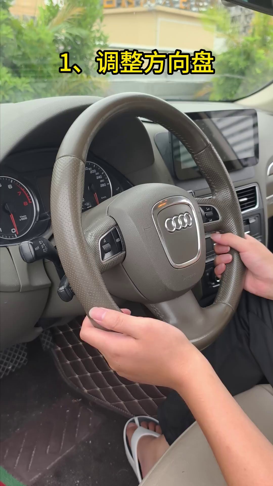
Sänk rattstången och lossa det nedre dammskyddet
Flytta ratten till sitt lägsta praktiska läge för att skapa arbetsutrymme framför fabriksklustret. Lossa det nedre dammskyddet / nedre listen försiktigt istället för att dra klustret mot det.
- Gör: skapa tillräckligt med utrymme för att klustret ska kunna röra sig framåt utan att skrapa mot listen.
- Kontrollera: det nedre skyddet ska röra sig fritt och ska inte förbli fastkrokat mot klustrets kant.
- Undvik: att bända direkt mot klustrets klara yta eller tvinga en listkant som inte har lossnat.
- Stoppa om: listen gör starkt motstånd; kontrollera de kvarhållna punkterna igen innan du använder mer kraft.
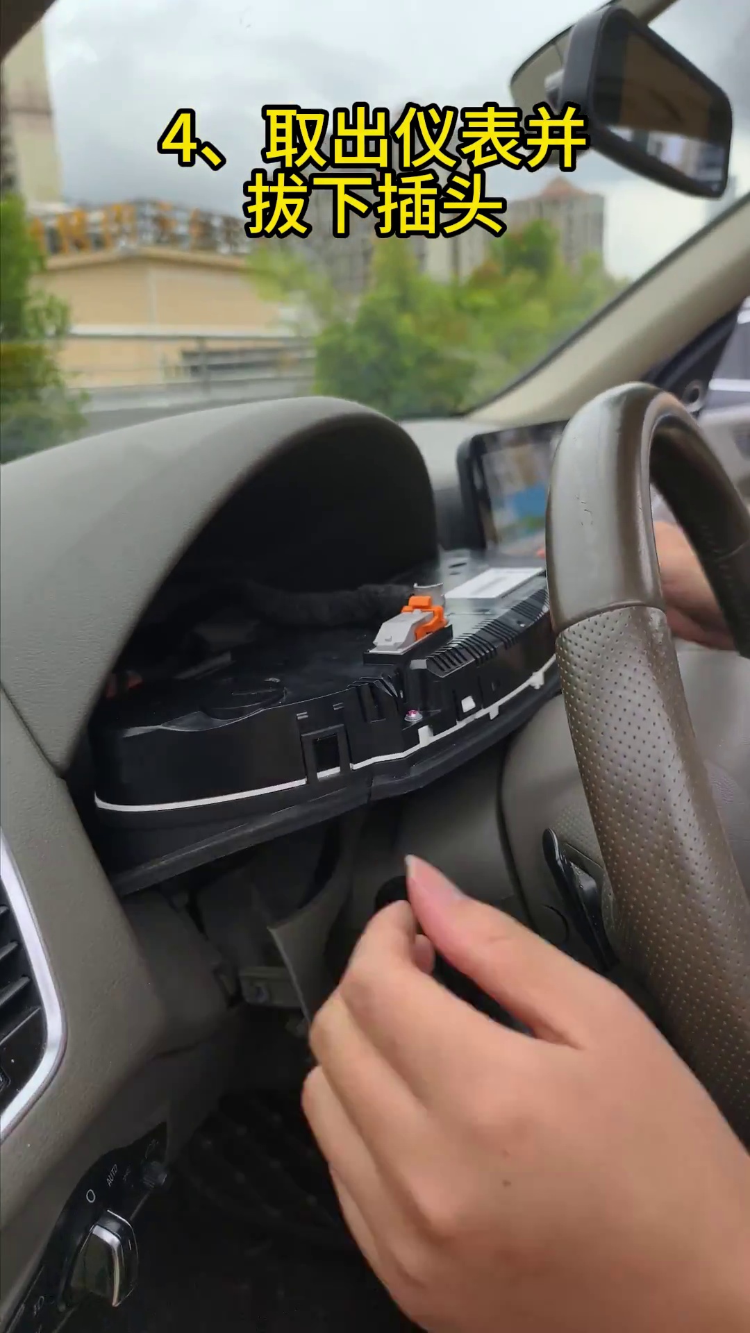
Ta bort de kvarhållna skruvarna, dra klustret framåt och koppla bort fabrikskontakten
Ta bort de ursprungliga kvarhållna skruvarna. Stöd klustret med båda händerna, för det framåt i en kontrollerad rörelse och kom sedan åt fabrikskontakten. Lossa kontakten med dess låsmekanism istället för att dra i kabelbunten.
- Gör: stöd klustret medan den sista fästpunkten lossas.
- Kontrollera: kontakten och terminalerna ska se raka och oskadade ut efter frånkoppling.
- Undvik: att vrida kontakten, dra i kablar eller placera det borttagna klustret med framsidan nedåt på en hård yta.
- Nästa: flytta det kompletta originalklustret till en ren vadderad bänk eftersom dess elektronik krävs för eftermonteringsvägen.
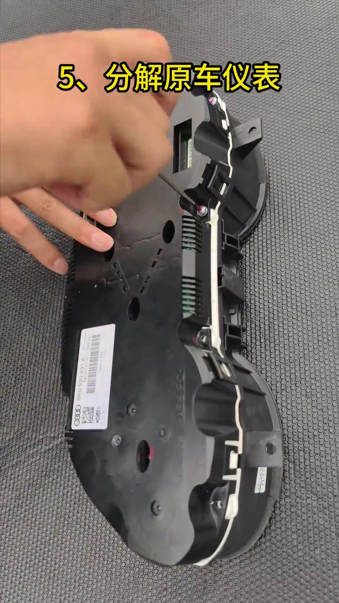
Hur överför du elektroniken från originalklustret i Audi Q5 8R till det digitala klustret?
Öppna donatorklustret på en ren, vadderad och statiksäker arbetsyta
Placera det ursprungliga mekaniska klustret på en vadderad bänk. Innan du rör PCB:n, ladda ur kroppsstatisk elektricitet genom att röra vid jordad metall. Öppna höljet försiktigt och håll borttagna skruvar och höljesdelar grupperade i sin ursprungliga ordning.
- Hantera PCB-kortet genom att hålla i kanterna. Undvik att röra chip, lödda komponenter och kontaktytor.
- Håll hårdvaran organiserad. Blanda inte skruvar från olika höljespositioner.
- Inspektera före överföring. Leta efter befintliga skador, föroreningar eller tidigare reparationsmärken.
- Stoppa om: donatorkortet är synligt skadat eller instrumentklustret har modifierats på ett sätt som inte matchar den dokumenterade vägen.
Inspektera originalklustret för det lilla hjälpkortet och överför det när det finns
Vissa mekaniska kluster med högre specifikation innehåller ett litet hjälpkort bakom den ursprungliga lilla displayen. Om ditt donatorkluster har detta kort måste det placeras och säkras inuti den nya LCD-klusterenheten enligt den medföljande vägen. Om donatorklustret inte har kortet ska du inte lägga till ett bara för att ett annat fordon har det.
- Titta först: inspektera bakom den ursprungliga lilla displayen innan du kasserar eller stänger några donatordelar.
- Om det finns: säkra kortet i den erforderliga positionen så att det inte kan röra sig inuti det nya höljet.
- Varför: ett utelämnat eller löst hjälpkort kan associeras med felaktig bränsleindikering eller instrumentvarningar på tillämpliga versioner.
- Före stängning: jämför kortets position med referensbilden och bekräfta att det inte trycker mot LCD:n eller kablarna.
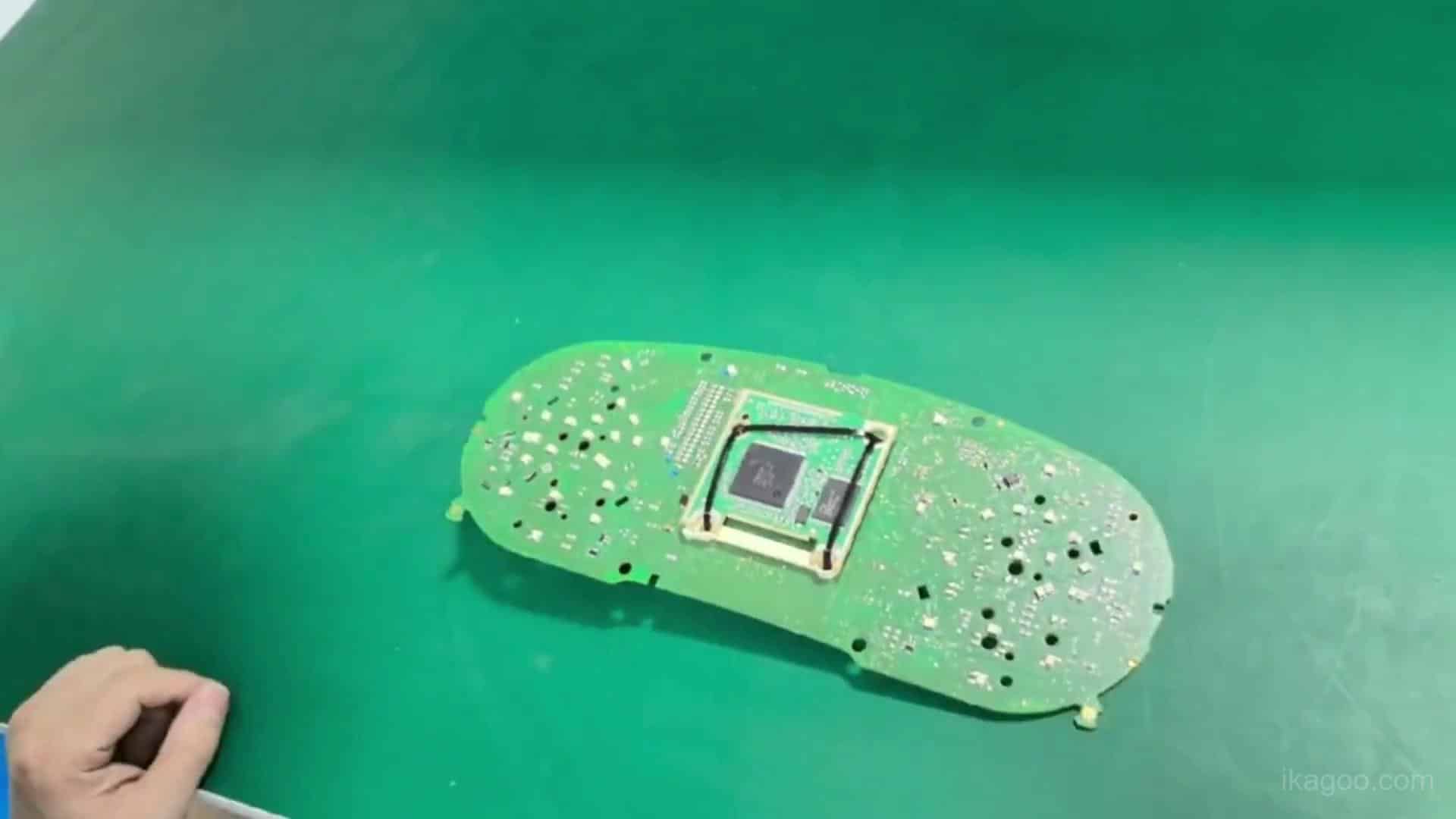
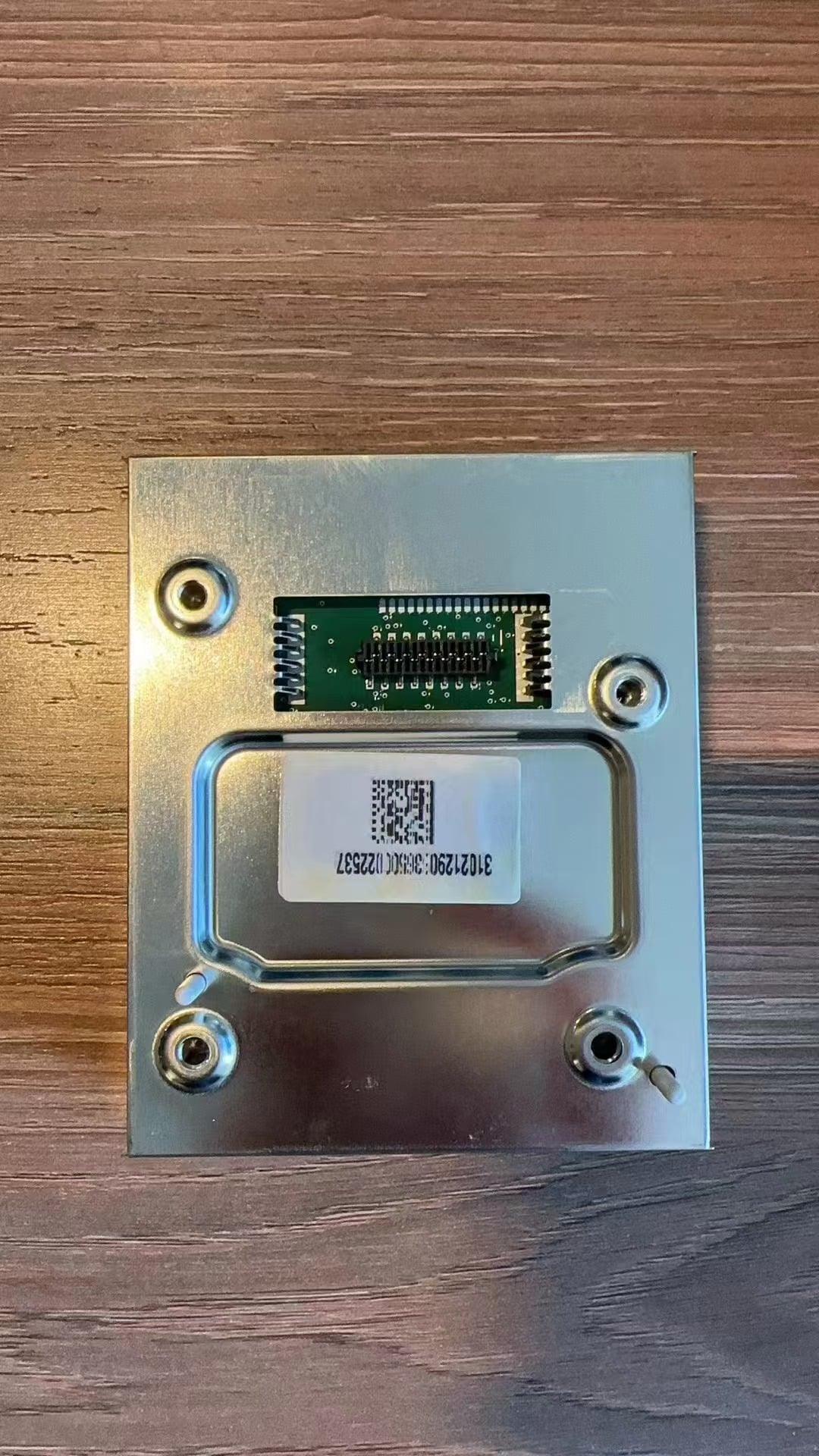
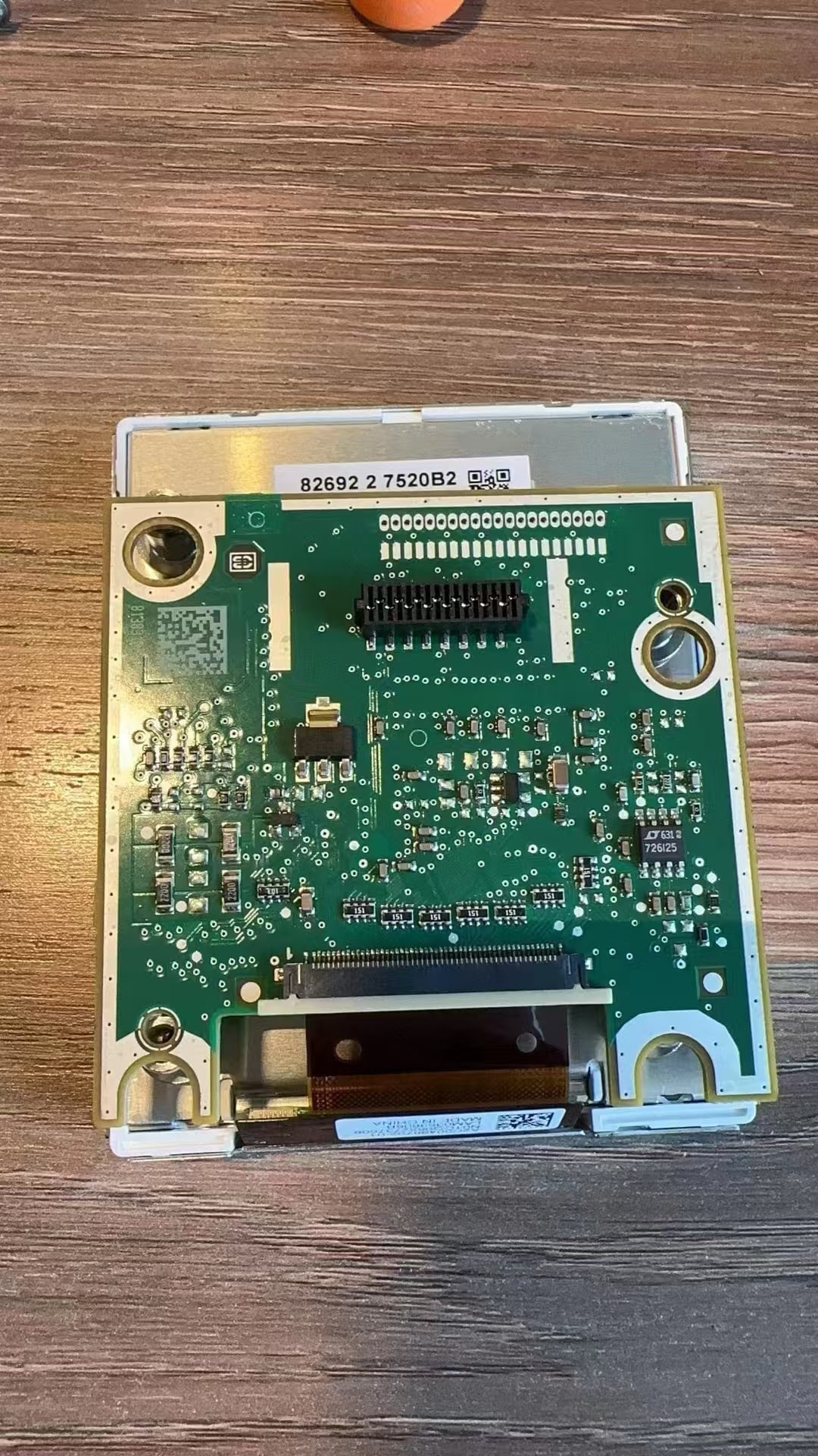
Överför originalets huvudkort till det nya digitalklusterhöljet
Flytta det bevarade originalhuvudkortet till den nya digitalklusterenheten utan att böja eller vrida det. Rikta in monterings- och anslutningspunkterna innan du applicerar tryck. Håll PCB:n platt och se till att hjälpkortets väg, där tillämpligt, redan har hanterats korrekt.
- Placera kortet plant: ingen hörn ska förbli lyft eller under spänning.
- Anslut kontakterna helt: lämna inte en flatkabel, sockel eller anslutningspunkt delvis ansluten.
- Håll kablarna fria: ingen kabel ska passera under en PCB-kant eller höljesskruvpunkt.
- Före stängning: inspektera visuellt kortets hela omkrets och bekräfta att inget är fastklämt.
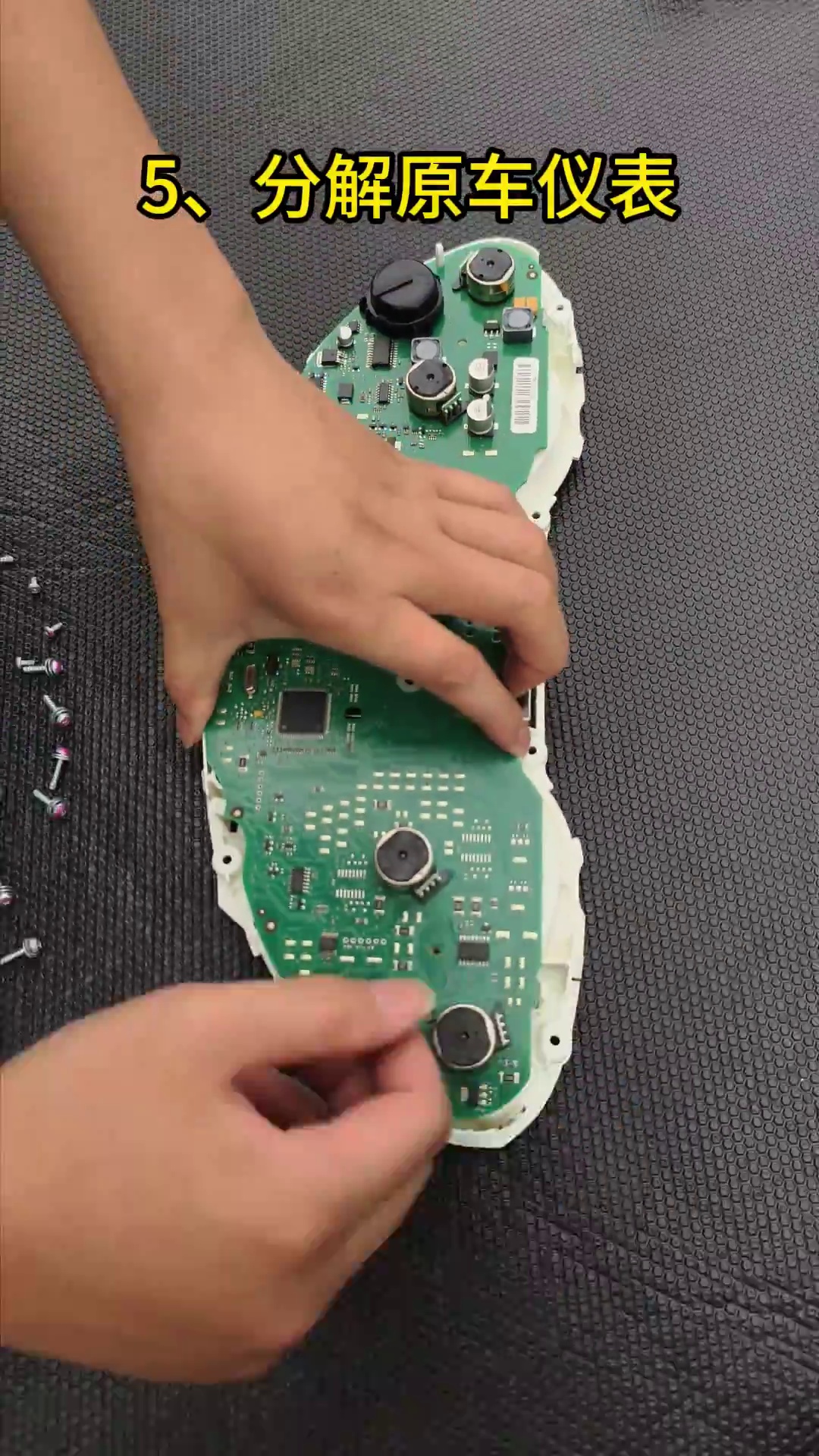
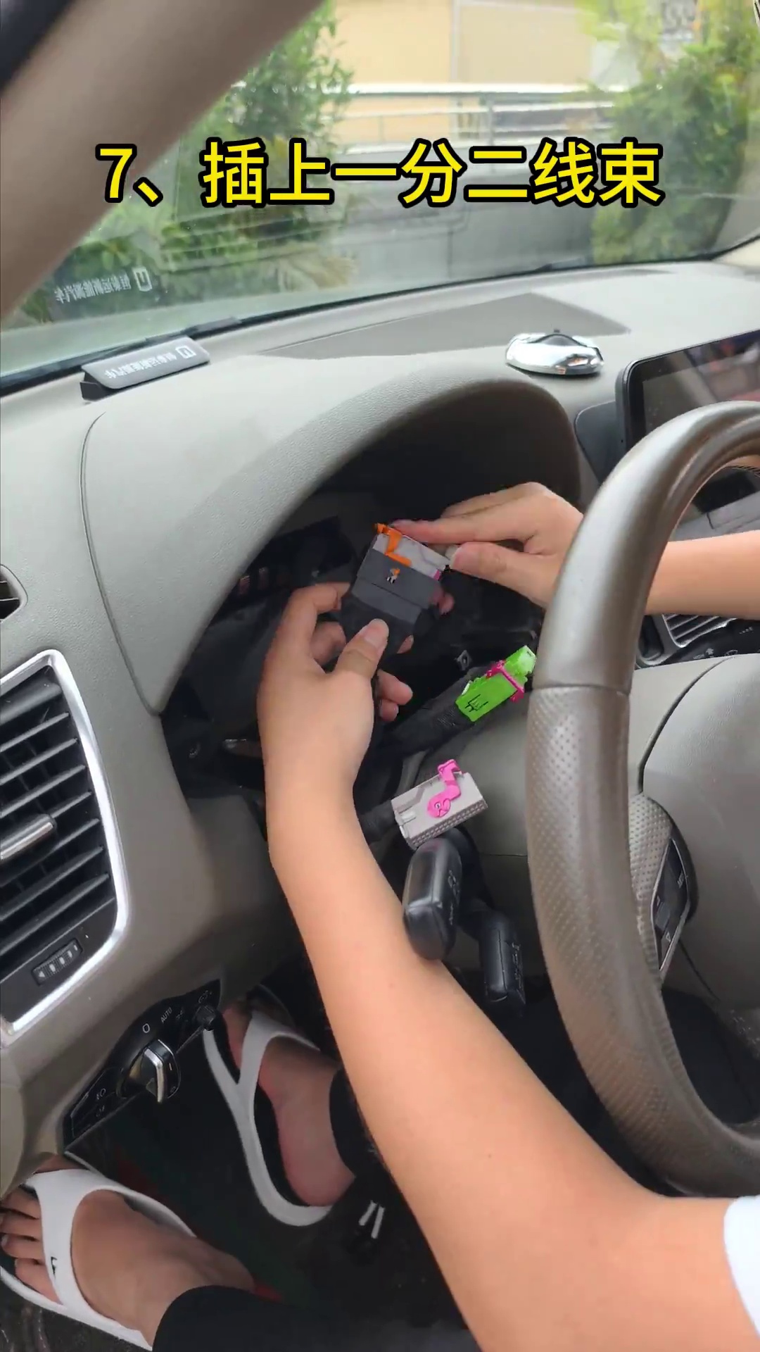
Anslut den matchade plug-and-play-kabelstammen och dra båda USB-kablarna innan du sätter klustret på plats
Anslut den medföljande matchade kabelstammen till rätt anslutningspunkter utan att klippa eller skarva i fordonets fabrikskablage. Rikta in varje kontakt innan du trycker den på plats. I samma steg, dra de två medföljande USB-kablarna mot ett tillgängligt nedre förvaringsutrymme nära ratten där det är praktiskt möjligt.
- Betydelse av plug-and-play: ingen klippning eller skarvning av originalkablaget; demontering av instrumentbrädan och överföring av elektronik krävs fortfarande.
- Kabelstamskontroll: varje kontakt ska vara helt isatt och kabelstammen ska ha tillräckligt med slack för att undvika spänning.
- USB 1: håll den kabelanslutna USB-porten för programvaruuppdatering tillgänglig.
- USB 2: håll den kabelanslutna speglings-/projicerings-USB som stöds tillgänglig där den medföljande klusterversionen erbjuder denna funktion.
- Undvik: klämma kabelstammen eller USB-kablarna bakom en vass kanten på höljet när klustret trycks tillbaka in i instrumentbrädan.
Var ska Audi Q5 digitala klusters USB-kablar lämnas efter installation?
Direkt svar
Begrav inte de medföljande USB-kablarna permanent bakom instrumentbrädan. Håll USB:n för programvaruuppdatering och, där den medföljande versionen stöder det, den kabelanslutna projicerings-/skärmspeglings-USB:n nåbar från ett praktiskt nedre förvaringsutrymme nära ratten.
Före slutlig isättning: dra försiktigt i varje USB-kabel från den planerade åtkomstpunkten och bekräfta att den förblir fri. Lämna tillräckligt med slack så att kontakten inte belastas när klustret trycks på plats.
Varför detta är viktigt: framtida programvarustöd eller en kontroll av kabelansluten projicering som stöds bör inte kräva onödig demontering av instrumentbrädan.
Versionsgräns: USB-funktioner kan variera beroende på medföljande hårdvaru-/programvaruversion. Behåll den fysiska åtkomstvägen, men hävda endast de USB-funktioner som bekräftats för det exakta kluster som medföljer.
Vad måste testas innan Audi Q5 8R instrumentbräda stängs?
Slå på det digitala klustret innan slutlig fastsättning
Med klustret anslutet men fortfarande åtkomligt, slå på tändningen och låt LCD-skärmen starta. Stäng inte den nedre listen ännu. Jämför den nya displayen med fotona som togs före borttagningen.
- Uppstart: bekräfta att LCD-skärmen slås på normalt och inte startar om upprepade gånger.
- Skärmens skick: kontrollera för linjer, mörka tryckområden, sprickor, onormala ljusa områden eller synlig skada på panelen.
- Varningar: jämför varningslampor/-meddelanden med den ursprungliga inspelningen av det påslagna klustret.
- Grundläggande fordonsdata: bekräfta att den synliga information som förväntas för den bekräftade fordonsvägen finns innan instrumentbrädan stängs.
- Om ett nytt problem uppstår: stanna och kontrollera det överförda huvudkortet, eventuellt hjälpkort, kabeldragning och kontakternas placering innan du överväger programvara.
LCD-säkerhet: tryck inte på skärmytan under testning eller montering. Sprickor och mörka tryckmärken är fysiska hanteringsproblem och kan inte repareras av programvara.
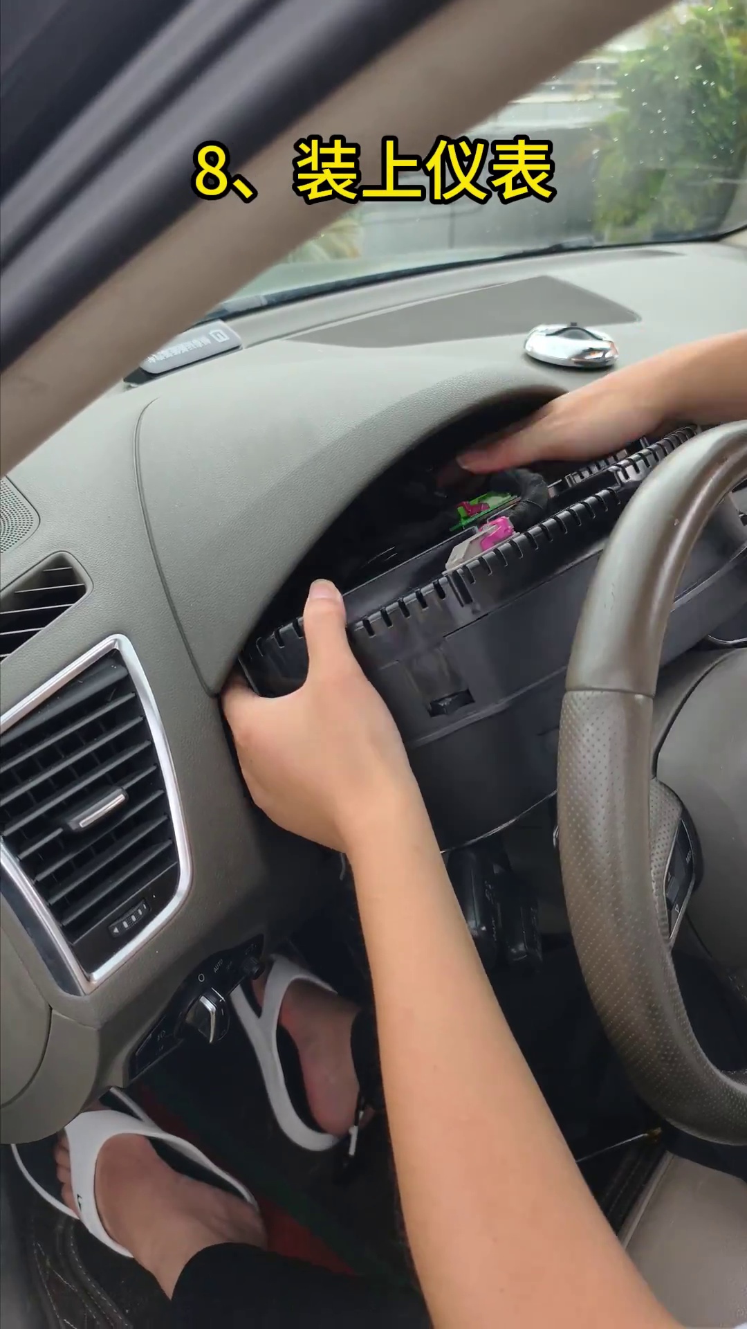
Montera klustret jämnt, sätt tillbaka de bevarade skruvarna och stäng den nedre listen
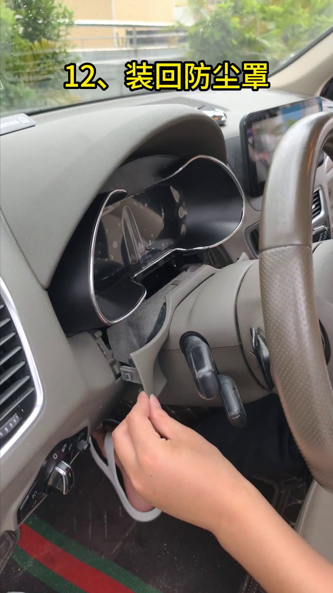
Först efter att steg 07 har godkänts bör klustret flyttas till sin slutliga position. Led kabelstammen och USB-kablarna bakom det utan att vika dem skarpt. Sätt tillbaka de bevarade fästskruvarna och montera sedan tillbaka det nedre dammskyddet / listen.
- Passform: det digitala klustret ska sitta jämnt i öppningen utan att ena sidan tvingas inåt.
- Kabelavstånd: ingen kabelstam eller USB-kabel bör klämmas mellan höljet och instrumentbrädans struktur.
- Nedre dammskydd: justera endast där det faktiska avståndet kräver det; ta inte bort mer material än nödvändigt.
- Slutlig tryckkontroll: den återmonterade listen får inte trycka mot LCD-ytan eller klusterhöljet.
- Slutlig tändningskontroll: starta fordonet igen efter stängning och bekräfta att skärmtillståndet inte har ändrats.
Hur kalibrerar du bränslemätaren efter en Audi Q5 8R digital kluster-retrofit?
Direkt svar
Fyll bränsletanken helt, kör några hundra meter och öppna sedan Kördata → Påfyllningsbar mängd. Använd den visade påfyllningsbara mängden som värdet som anges under Inställningar → Konfiguration Kalibrering → Bränsletankens kapacitet. Efter lyckad kalibrering bör den påfyllningsbara mängden återgå till 0 och bränslemätaren bör visa full.
- Fyll fordonets bränsletank helt.
- Kör några hundra meter så att skärmtillståndet uppdateras.
- Öppna Kördata → Påfyllningsbar mängd och notera det värde som visas.
- Öppna Inställningar → Konfiguration Kalibrering → Bränsletankens kapacitet.
- Ange värdet för påfyllningsbar mängd som registrerades i föregående steg.
- Kontrollera skärmen igen. Den påfyllningsbara mängden bör återgå till 0 och mätaren bör indikera full tank.
Om resultatet fortfarande är fel: på fordon vars donatorkluster innehöll det lilla hjälpkortet, bekräfta att kortet behölls och fixerades korrekt innan du upprepade gånger ändrar kalibreringsvärden.
Håll Physical Light inaktiverat om den här inställningen visas i den medföljande klusterprogramvaran
Direkt svar: Om den medföljande programvaran visar ett Fysiskt ljus alternativ, håll det inaktiverat om inte den dokumenterade korrigeringsvägen specifikt kräver att det kontrolleras, eftersom en felaktig inställning kan påverka visningen av körriktningsvisaren.
Justera grafik för visning av fordonsmodell endast efter att hårdvaruinstallation har bekräftats
Om den lilla grafiken för fordonsmodellen inte stämmer överens med det verkliga fordonet, ange Inställningar → Val av fordonsmodell. Välj den matchande modellen där den finns tillgänglig. Efter valet, stäng av fordonet, lås det och vänta några minuter. Detta ändrar endast den synliga modellgrafiken. Det ersätter inte bekräftelsen av hårdvarukompatibilitet. Varför det är viktigt: Läsare förväxlar ofta en avvikelse i visningsmodell med en hårdvaruavvikelse. Menyn ändrar endast den synliga grafiska rutten. Så här kontrollerar du: Ändra modellgrafiken, lås fordonet och vänta några minuter innan du kontrollerar det nya displayläget. Om det hoppas över: Kunden kan anta att hårdvaruvägen är fel även om endast den synliga bilmodellikonen behöver justeras.Slutlig checklista innan Audi Q5 återgår till normal användning
| Kontrollera objekt | Vad du ska kontrollera | Om den inte klarar det |
|---|---|---|
| Displaystart | LCD-skärmen startar normalt under den första kontrollen vid tändningspåslag. | Stoppa slutlig stängning och kontrollera igen kortöverföringssteget och kontaktsättningen. |
| Hjälpkort, litet kort vid behov | Om den ursprungliga instrumentpanelen hade det lilla kortet, bekräfta att det var fastsatt och installerat korrekt. | Öppna monteringen igen och korrigera hjälpkortets position innan du skyller på programvaran. |
| Skärmens skick | Inga linjer, mörka tryckområden, sprickor eller glasskador är synliga. | Sluta hantera displayen; fysisk panelskada åtgärdas inte med programvara. |
| Jämförelse av synliga varningar | Jämför de aktuella varningarna med posten före installationen. | Undersök nyuppkomna varningar i stället för att behandla dem som förväntade. |
| Bränslevisning | Efter tankning, bekräfta mätarens beteende och logiken för påfyllningsbar mängd. | Kontrollera det lilla kortet om tillämpligt, och utför sedan kalibrering av bränsletankens kapacitet. |
| Blinkersvisning | Bekräfta visningsbeteendet för vänster och höger blinkers. | Kontrollera att Physical Light inte är felaktigt aktiverat om den här inställningen visas i den medföljande programvaruvägen. |
| Åtkomst till USB-kabel | Uppdaterings-USB och det USB för stödd projicering förblir åtkomliga. | Korrigera kabeldragningen innan instrumentbrädan stängs helt. |
| Passform och trim | Instrumentklustret sitter jämnt och den nedre listen trycker inte mot displayen. | Öppna trimsteget igen och kontrollera frigång endast där justering faktiskt behövs. |
| Stödda funktioner | Verifiera endast de funktioner som bekräftats för det medföljande fordonet och produktvägen. | Anta inte att alla funktioner bevaras universellt; jämför mot den bekräftade baslinjen. |
| Foto av programvaruversion | Behåll ett foto av skärmen för den installerade versionen innan eventuell senare uppdatering. | Tillämpa inte online- eller USB-uppdateringspaket blint på en oregistrerad version. |
Hur denna installationsguide för Audi Q5 8R utarbetades och verifierades
Denna artikel underhålls av iKAGOO:s tekniska team för den dokumenterade eftermonteringsvägen till digitalt instrumentkluster för första generationens Audi Q5 / SQ5 8R på denna sida. Instruktionerna baseras på de fordonsspecifika installationsfotografierna, referenserna för överföring av donatorkort, exemplen på hjälpkort, videokontrollpunkterna, kontrollerna vid första strömtillförseln och kalibreringsstegen efter installation som visas i guiden.
Installationsbevis från första hand
Artikeln använder faktiska bilder från installationsstegen för Q5 8R som täcker borttagning av klustret, öppning av donatorklustret, överföring av originalkortet, anslutning av kabelstammen, strömtillförseltest och återmontering av den nedre panelen.
Kompatibilitet antas inte utifrån ett emblem
Q5, SQ5, TFSI, TDI, quattro, Premium, Premium Plus eller Prestige-formuleringar behandlas inte som automatiskt bevis på kompatibilitet. iKAGOO kontrollerar fordonsår, originalklustret med strömtillförsel, instrumentpanelens utformning och LHD/RHD-konfiguration.
Kända begränsningar anges öppet
Delade Audi/VW-menyreferenser, USB-projektionsbeteende, uppdateringsvägar och bevarade funktioner kan variera beroende på levererad version. Guiden skiljer bekräftad installationslogik från versionsberoende beteende.
Granskad: 2 september, 2026
Omfattning: kompatibel eftermonteringsväg för mekaniskt kluster på Audi Q5 / SQ5 8R, med en iKAGOO-passningsgräns på 2009–2017.
Redaktionell regel: om det exakta fordonet eller det levererade klustret inte matchar en dokumenterad väg, instruerar artikeln installatören att stanna och verifiera i stället för att anta kompatibilitet.
Stödd väg för uppgraderingspaket för Audi / Volkswagen digital instrumentpanel
FixMyDash är till för köp av programvaruuppgraderingspaket för digitala kluster för kompatibla Audi / Volkswagen och support relaterad till paketet. Det är en separat supportväg för kompatibla befintliga digitala kluster. Det är inte en tjänst för hårdvarureparation. Det lovar inte att reparera skärm skador, skadade kort, kablagefel, felaktig installation, kommunikationsfel eller orelaterade fordonsproblem. Köp stödd uppgraderingspaket Kontrollera online- / USB-uppdateringsguidenBehöver du den matchande Audi Q5 8R digitala instrumentpanelen för 2009–2017?
Kunder som letar efter den kompletta iKagoo Audi Q5 8R digitala instrumentpanelens hårdvarulösning för kompatibla 2009–2017 Audi Q5 / SQ5 8R-modeller bör använda den matchande produktsidan och bekräftelse av passform innan beställning. Visa Audi Q5 Digital Instrument Cluster-produkt Bekräfta passform med iKagooAudi Q5 8R Virtual Cockpit Installationsfrågor
Är denna guide för europeiska och nordamerikanska Audi Q5 8R-modeller?
Ja, guiden är skriven kring den mekaniska klustervägen för första generationens Audi Q5 / SQ5 8R som används av ägare i Europa och Nordamerika. iKAGOO-passningsgränsen på denna sida är fortsatt 2009–2017. Amerikanska modellår 2018 och senare Q5-fordon är en annan generation. Europeiska fordon som först registrerades 2008 kräver individuell bekräftelse innan denna hårdvaruväg 2009–2017 används. Motor- eller utrustningsformuleringar som TFSI, TDI, quattro, Premium, Premium Plus, Prestige eller SQ5 ersätter inte fotobekräftelse av originalklustret.








Add comment
Du måste vara inloggad för att publicera en kommentar.